
When “off-grid” we rely on an Onan Emerald II 4KW generator for battery charging and 110 VAC requirements. Typically in the winter time we run the generator 1 hour for breakfast, 1 hour for lunch and 1-2 hours in the evening for supper. My theory is that allowing the batteries to rest in between charging cycles somehow gives me more bang for my generator run-time dollar by allowing the surface charge to work its way onto the plates.
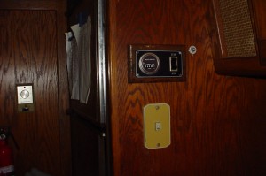
By no longer needing to go outside to start the generator, this little luxury turned out to be worth more to me than I thought it would at the time.
So one year ago, September 2017, hurricane Irma traversed the state of Georgia. We chose to wait until the appropriate time and drive 100 miles perpendicular to Irma’s projected track, or Augusta, Georgia where we found safety parked snugly in between tractor trailers in a truck stop. However when I pressed the button to summon electricity to microwave lunch nothing happened. No emergency on our part, we used propane to cook and if necessary the chassis engine will charge the battery pack. Being low on my priority list trouble shooting the problem sat until now, when I noticed that the governor rod was beginning to hang up where it comes out of the engine case.
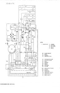
This is one-half of the manual page of electric cartoons and schematics for our generator detailing the control board.
So now that the heat of summer in South East Georgia has broken it was time to begin trouble-shooting the control board. We had run the factory test on the control board while sheltering in Augusta and found the board to have a problem, so I began by checking the ground for the board. You can never have too good an electrical ground. I checked and found it to be good. So I brought the board inside and settled down for the long hard slog, board in hand and what I call the ladder logic schematic by my side.
Because I have short term memory problems the only way I can do this sort of work is to pretty much memorize the entire schematic, something I avoid as much as possible these days. But, I understand that the built in battery charger has to work because it’s part of the run circuit. If one works, the other does too. I also saw that the start contact grounded the coil for coil K4 and K3 sending power to the starter relay and the ignition system. The field flash, to kick start the alternator, comes in from normally closed contact on K2 taking power from the starting relay voltage line. That normally closed contact opens, stopping the field flash, as soon as the alternator begins generating.
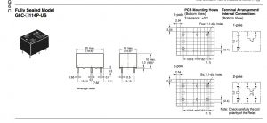
Omron G6C 2114P Contact Details
So what I knew going in was that there was no starter line voltage going out. I also knew that if I used a jumper to trigger the starter solenoid, the engine would crank and begin running, and the generator would run as long as I held the starter switch but not generate electricity. No field flash. The indicators point to the on-board Relay K4. Probing with a diode tester from the pin on K4 to the output pin #7 showed open. Testing from the blocking diode Crystal Rectifier 2 or CR2 to the pin showed a good circuit so it must be the relay. Oh I so desperately wanted to cut open that relay with my Dremel.
After sleeping on the matter I spent some time finding the pin-out for the relay on-line and double checked what I had already accomplished. Running all of the tests a second time with fresh eyes I realized that the relay was switching B+ to the output pin but the output pin wasn’t connected to the trace. One inch of #24 AWG wire under the board solved the problem, and saved me $129.00 because lucky for all of us running obsolete Onan Emerald II generators, Dinosaur Electronics manufactures the exact replacement control board for our Onan’s.
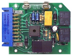
Dinosaur Electronics Onan Control Board O_300_4901 for the Emerald II generator.